
In the electronics industry, transistors are a fundamental and crucial type of semiconductor device, widely used in various circuits. Many electronics enthusiasts and engineers often search on Google for how transistors work, especially the specific applications of different models. This article will explain, in a simple and easy-to-understand way, the basic definition and working principle of transistors, and provide an in-depth look at six common modes of operation: NPN transistor, PNP transistor, NPN transistor with a pull-down resistor, PNP transistor with a pull-up resistor, NPN transistor driving a buzzer, and NPN transistor driving a relay.
Catalog
V. NPN Transistor with Pull-Down Resistor
VI. PNP Transistor with Pull-Up Resistor
VII. NPN Transistor Driving a Buzzer
VIII. NPN Transistor Driving a Relay
I. What is a Transistor?
A transistor (Bipolar Junction Transistor, BJT) is a semiconductor device with three terminals: Base (B), Collector (C), and Emitter (E). Its structure can roughly be seen as two PN junctions connected in series (e.g., N-P-N or P-N-P). The base controls the majority of the carriers injected from the emitter to flow toward the collector, achieving current amplification and switching functions. In the electronics industry, transistors are classified by polarity into NPN and PNP types and further subdivided by power, frequency, and packaging. In short, it is a classic "small current controls large current" device, perfect for signal amplification, logic switching, and driving loads.
II. Working Principle
The working principle of a transistor is based on current control. When a sufficient forward voltage (usually 0.6V to 0.7V) is applied between the base and emitter, the base current flows and controls the current between the collector and emitter. A transistor operates in three states: cutoff, active (amplification), and saturation. In saturation, the transistor is fully on, like a closed switch; in cutoff, it is off, like an open switch. The base current usually needs to reach at least 1mA to ensure the transistor reliably enters saturation, at which point the collector current can reach tens to hundreds of milliamps, enough to drive relays, buzzers, and other power devices.
III. NPN Transistor
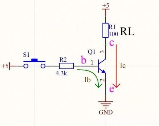
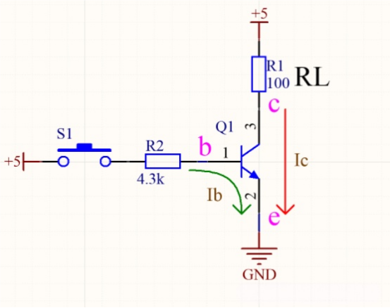
For an NPN transistor, the arrow points from the base to the emitter. When a high voltage is applied to the base (e.g., pressing switch S1), a clamping voltage of about 0.6V–0.7V appears between base and emitter, and the base current Ib flows into the emitter, putting the transistor into saturation. At this point, the collector and emitter conduct, the collector voltage approaches ground (GND), and the voltage across the load is close to the supply voltage (e.g., 5V). In an NPN transistor, both the base and collector currents flow into the emitter, so the emitter is usually connected to ground and the collector to the load and power supply.
IV. PNP Transistor
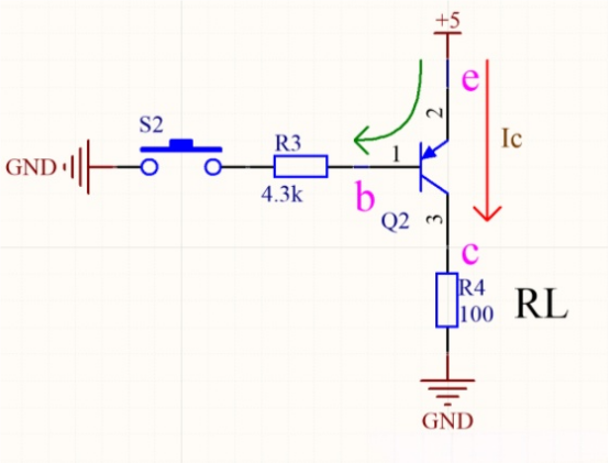
For a PNP transistor, the arrow points from the emitter to the base. When a low voltage is applied to the base (e.g., pressing switch S2), the same 0.6V–0.7V clamping voltage appears between base and emitter, and the base current Ib flows out of the emitter, putting the transistor into saturation. At this point, the emitter and collector conduct, the collector voltage approaches the supply voltage, and the voltage across the load is close to the supply. In a PNP transistor, both the base and collector currents flow out of the emitter, so the emitter is usually connected to the power supply, and the collector to the load and ground.
V. NPN Transistor with Pull-Down Resistor
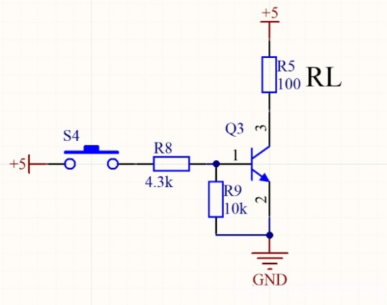
Adding a pull-down resistor (usually 2–10kΩ) to the base of an NPN transistor serves two important purposes: first, it accelerates the discharge of the base-emitter capacitance, helping the transistor turn off faster; second, it ensures a defined low logic level at the base, preventing instability caused by a floating or high-impedance control input. In design, make sure the voltage divider formed by the base resistor and pull-down resistor exceeds 0.7V to ensure proper conduction.
VI. PNP Transistor with Pull-Up Resistor
For a PNP transistor, adding a pull-up resistor (usually 2–10kΩ) works similarly: it speeds up turn-off and ensures the base remains at a defined high level in high-impedance conditions, preventing false triggering. Design must ensure the voltage divider formed by the base resistor and pull-up resistor satisfies the conduction requirement.
VII. NPN Transistor Driving a Buzzer
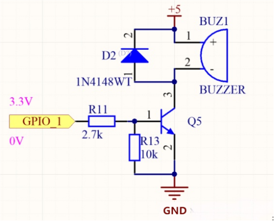
When using an NPN transistor to drive an inductive load like a buzzer, a reverse flyback diode must be connected across the load. When the transistor switches off, the inductive load generates reverse EMF, and the diode provides a path for the current, clamping the reverse voltage and preventing transistor damage. The diode should be a fast-recovery or Schottky diode to ensure quick response.
VIII. NPN Transistor Driving a Relay
When driving a relay or other devices requiring low-level control, if the control signal is not fully 0V (e.g., there may be residual voltage under 1V), a reverse zener or forward diode can be connected in series with the NPN transistor base to raise the conduction threshold, ensuring the transistor fully turns off at low-level signals. This is optional for push-pull outputs but necessary for open-collector or delayed control circuits. The zener should conduct at ≥1mA.
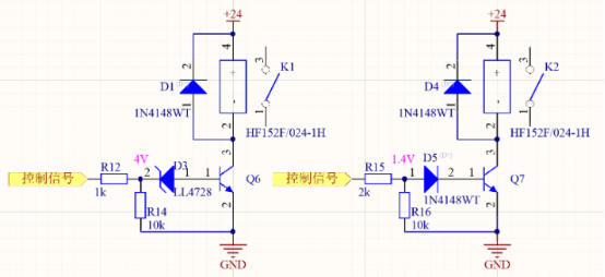
For NPN transistors, the voltage divider of the base and pull-down resistors must exceed 0.7V; the same applies to PNP transistors. The base current should be ≥1mA to ensure the transistor enters saturation, allowing the collector current to reach its maximum driving capacity. The transistor's current gain β indicates the multiplication of current-driving capability, not the actual current value.
IX. Conclusion
When designing transistor switch circuits, pay attention to the following: for NPN transistors, the base and pull-down resistor voltage divider must exceed 0.7V to ensure proper forward bias; PNP transistors follow the same rule. Base current should be at least 1mA to guarantee saturation and full driving capability. Also, the current gain β represents the amplification of current-driving capability; for example, β = 100 means the output current can be amplified 100 times, not that the actual current value itself is multiplied.


