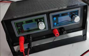
After using a boost-buck module for a long time, having to constantly check voltage and current with a multimeter can get really inconvenient. If you've run into this problem, follow this guide to DIY a customizable adjustable power supply that suits you perfectly.
You'll need: one WZ10020L buck module, one ZK-5KX boost-buck module, a 20017570 plastic instrument case, four 4mm banana jacks, one 5521 DC connector, one 5.08 through-wall terminal, one XT60 panel male connector, and two meters of 12AWG silicone wire. With these components, you can assemble an adjustable power supply directly. This article will skip the assembly process.
Here's a schematic of the adjustable power supply:
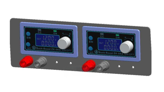
The two meters are basically the same, so you can just draw one of them.
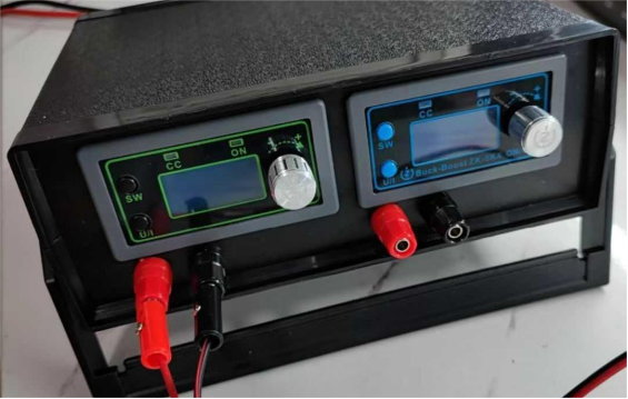
The front output section looks like this: the left side is the high-power buck module, mainly connected to an electric bike battery. Input range: DC 10–110V, output: 0–100V, max current: 20A. The right side is the boost-buck module, connected to a small battery or ATX input. Input range: DC 6–36V, output: 0.6–36V, max current: 5A. You'll need to reserve two banana jacks for the output. If the panel XT60 connector doesn't fit, you'll need to adjust it yourself.
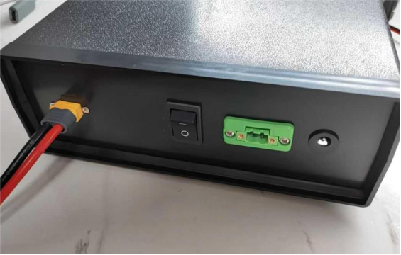
The rear input section looks like this: the middle is the main switch. On the left is an XT60 connector for the electric bike battery, using 12AWG wire. On the right are a 5.08 panel terminal and a 5521 DC socket. These can connect to either a battery or an ATX power supply.
The internal structure looks like this: you can wire it a bit better if you want.
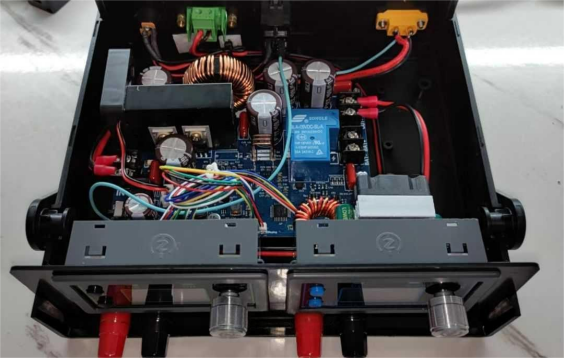
For dual power input, see the diagram below, which shows the input voltage.
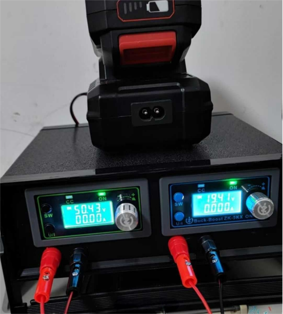
If you want to make one, get started right away!
The End.


